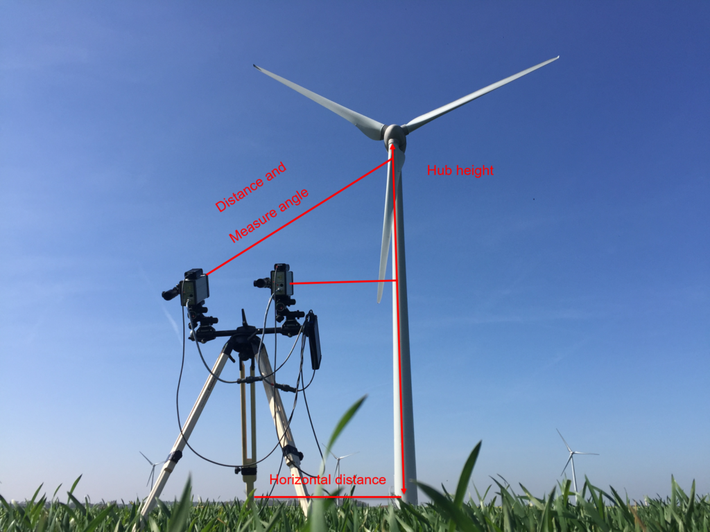
Measurement configuration with the ROMEG
The ROMEG system consists of two high-frequency lasers positioned upwind of the rotor at a distance approximately equal to the hub height. These two lasers scan the blades in two positions, as well as the position of the tower between each blade passage. The result is a graph showing the averaged profile of each of the 3 blades, as well as a graph showing the movements of the tower depending on the rotor rotational speed.

Illustration of blade profiles measured by the ROMEG
Profiles with 0.2° deviation
Profiles with 0.6° deviation
Profiles with 1.2° deviation

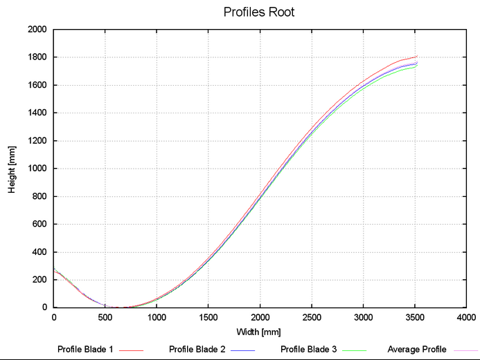
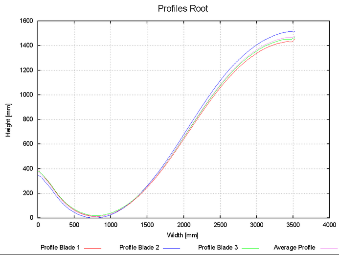
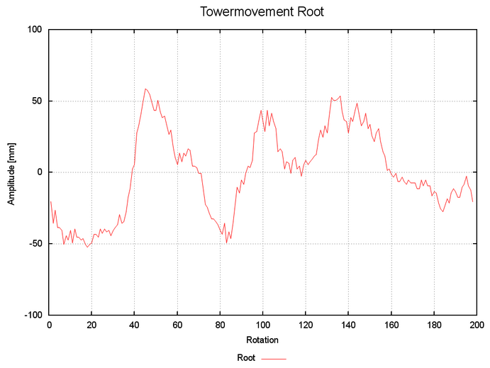
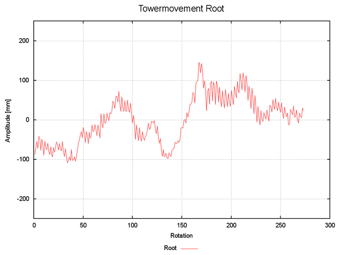
Illustration of tower oscillations measured by the ROMEG
Oscillations with 0.2° deviation
Oscillations with 0.6° deviation
Oscillations with 1.2° deviation

Different ROMEG control points

Tolerances
Relative pitch angles +/- 0.15°
Radial splitting +/- 0.2°
Tower clearance +/- 50mm
Twist angle +/- 1°
Axial tower oscillation +/- 10mm